

At a Glance
Section | Summary |
Overview and Fundamental Operation | Explores the core architecture, functional necessity, and foundational topology of an off-grid inverter operating in fully isolated microgrid applications. |
Pure Sine Wave Inverter | Analyzes total harmonic distortion (THD), sine wave generation, and why pure sine wave off-grid inverter circuits are mandatory for delicate electronics and heavy industrial inductive loads. |
Surge Capabilities | Examines peak surge wattage, transformer topologies, high frequency versus low frequency transformer off-grid inverter dynamics, and starting current handling for heavy machinery. |
Efficiency and Self Consumption | Evaluates power conversion efficiency, tare loss, thermal dissipation, stand-by power consumption, and economic optimization of off-grid inverter topologies. |
System Integration and Selection Matrix | Provides technical matching guidelines for battery voltage, solar array input, ambient environmental protection ratings, and system topology configurations. |
Overview and Fundamental Operation
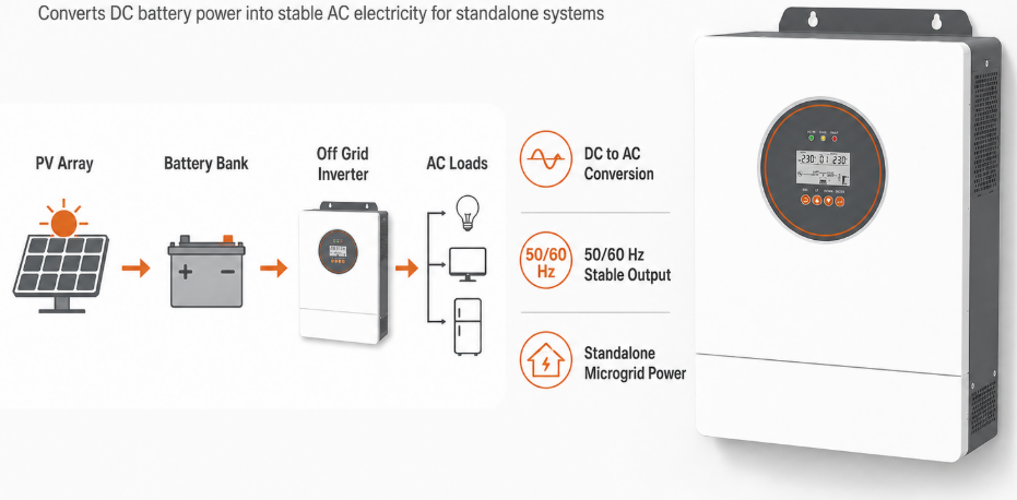
An off-grid inverter is a dedicated power conversion unit that transforms DC voltage from renewable sources or batteries into precise AC electricity to power standalone electrical loads independently of utility grids.
In off-grid solar energy harvesting systems, electrical energy is naturally harvested in direct current (DC) form by photovoltaic (PV) arrays and stored in secondary electrochemical battery banks (such as Lithium Iron Phosphate or Lead Acid). However, standard industrial machinery, household appliances, HVAC units, and commercial electronics are engineered to run on alternating current (AC) standard single phase or three phase voltages. The off-grid inverter fills this critical void by forming a local, self sustained AC grid voltage waveform, maintaining exact frequency (50Hz or 60Hz) and nominal RMS output voltage regardless of instantaneous fluctuations in solar irradiance or load dynamic swings.
Unlike grid tied inverters, which continuously sample the existing utility grid voltage waveform to synchronize their current injection phase, an off-grid inverter operates as a pure voltage source master. It creates its own sinusoidal phase reference and must actively manage load side dynamic imbalances, short circuit current faults, and high surge demands. Modern advanced off-grid inverter models incorporate intelligent Maximum Power Point Tracking (MPPT) solar charge controllers, internal AC transfer relays, and auxiliary diesel generator autostart terminals inside a unified chassis. This enables seamless, multi source energy orchestration for continuous 24/7 power availability.
When selecting systems for remote energy projects or hybrid microgrids, engineers often evaluate flexible conversion units. For installations requiring seamless switching between utility backup and completely independent battery energy storage, leveraging a robust hybrid on-off grid solar inverter system ensures dual mode operation capability, high PV tracking efficiency, and smart energy dispatching to lower lifetime operating expenditures.
Core Internal Subsystems of an Off-Grid Inverter
To fully understand off-grid inverter mechanics, one must examine the internal physical components responsible for high efficiency DC to AC inversion, thermal management, and circuit protection.
Subsystem / Component | Primary Function in Off-Grid Inverter | Technical Specification Benchmark |
DC Bus Filter and Inrush Limiter | Smooths DC input ripple current from battery bank and prevents high spark inrush during capacitor pre charge. | High temperature, low ESR electrolytic capacitor bank (105 degree C rated). |
IGBT / MOSFET Inverter H Bridge | Executes high speed Pulse Width Modulation (PWM) switching to generate raw AC waveform. | Gallium Nitride (GaN) or Silicon Carbide (SiC) MOSFETs / Insulated Gate Bipolar Transistors. |
LC Output Low Pass Filter | Filters out high frequency carrier switching noise (20kHz to 100kHz), yielding a smooth pure sine wave. | Ferrite core inductive choke with polypropylene film filter capacitors. |
Main Power Transformer | Provides galvanic isolation, steps up low battery voltage to utility levels, and absorbs high inductive motor spikes. | Toroidal low frequency copper transformer or ferrite high frequency transformer core. |
Microcontroller Unit (MCU/DSP) | Executes real time feedback loops for RMS voltage regulation, short circuit protection, and MPPT logic. | 32 bit dual core Digital Signal Processor (DSP) running high speed sampling routines. |
Pure Sine Wave Inverter
A pure sine wave off-grid inverter produces a smooth, continuous sinusoidal output voltage waveform that matches or exceeds the spectral quality of standard commercial power grids.
In power quality analysis, the structural integrity of an AC output waveform is measured by Total Harmonic Distortion (THD). Modern high grade pure sine wave off-grid inverter equipment achieves a THD of less than 3 percent under linear resistive loads and less than 5 percent under complex non linear switching loads. This pristine sinusoidal output is generated using high frequency Pulse Width Modulation (PWM) pulse trains controlled by advanced Digital Signal Processors (DSP). The DSP continuously compares a reference sine wave against the actual output voltage feedback loop, making microsecond level duty cycle adjustments to maintain a clean voltage curve even under sudden load step changes.
Earlier off-grid inverter generations utilized square wave or modified sine wave circuit architectures. While inexpensive, modified sine wave inverters introduce severe high order electrical harmonics into connected equipment. When powering sensitive loads such as medical diagnostics, telecommunication server racks, precision variable speed drives, or HVAC compressors, modified sine wave power causes substantial harmonic distortion losses. This results in excessive heat buildup in electric motor windings, visible line buzz on audio and video gear, nuisance tripping of micro controllers, and premature failure of internal power supplies. A pure sine wave off-grid inverter mitigates these issues entirely, ensuring universal appliance compatibility and extended equipment operating lifespan.
In demanding industrial environments exposed to ambient dust, high moisture, or abrasive airborne particles, choosing a ruggedized enclosure is paramount. Industrial projects operating in harsh outdoor conditions benefit immensely from deploying an IP54 weatherproof euro-standard off-grid inverter, which pairs pristine pure sine wave power conversion with heavy duty ingress protection for uninterrupted operational continuity.
Waveform Comparison: Pure Sine Wave vs. Modified Sine Wave Off-Grid Inverter
The operational contrasts between output waveform types are critical when engineering off-grid electrical networks.
Performance Metric | Pure Sine Wave Off-Grid Inverter | Modified Sine Wave Off-Grid Inverter |
Total Harmonic Distortion (THD) | Typically less than 3 percent (Resistive) / less than 5 percent (Non linear) | Typically 20 percent to 40 percent THD |
Inductive Load Heating | Minimal thermal losses; cool operation | High thermal losses; 15 to 30 percent temperature rise |
Equipment Compatibility | 100 percent universal compatibility across all loads | Incompatible with audio, medical, VFDs, motors |
Peak Voltage Control | Precise, stable RMS and peak voltage matching | Fluctuating peak to RMS ratios under varying loads |
Audible Noise Generation | Silent electrical operation; no motor hum | Loud mechanical buzzing in transformers and motors |
Surge Capabilities
Surge capability represents the momentary peak power output an off-grid inverter can deliver to initiate heavy inductive loads without collapsing system voltage or triggering internal overload protections.
Inductive electrical loads, such as water well pumps, refrigeration compressors, industrial air conditioners, power tools, and motorized conveyer systems, require immense starting current (locked rotor amperage) to establish their initial magnetic fields and overcome mechanical inertia. This surge demand typically ranges from 300 percent to 600 percent of the equipment continuous rated running wattage for a duration lasting anywhere from a few milliseconds up to 5 full seconds. An off-grid inverter must be oversized or specifically engineered with robust pulse current thermal reserves to absorb these massive short duration current demands without tripping its electronic protection thresholds.
The surge capacity of an off-grid inverter is largely governed by its underlying transformer topology. Off-grid inverters generally fall into two structural categories: Low Frequency (LF) transformer based architectures and High Frequency (HF) switching architectures. Low frequency off-grid inverter units utilize massive, heavy iron core toroidal transformers operating directly at 50Hz or 60Hz. The large magnetic mass of a low frequency transformer acts as an inductive energy flywheel, providing extraordinary overload reserves (typically 300 percent peak surge capacity for up to 10 seconds). High frequency off-grid inverter units replace iron transformers with compact ferrite cores operating above 20kHz. While HF off-grid inverter units are significantly lighter and cheaper, their surge duration is generally limited to 150 percent to 200 percent for less than 100 milliseconds due to the limited thermal mass of semiconductor components.
For installations demanding extreme surge tolerance, high overload margins, and integrated high voltage MPPT tracking capabilities, system designers frequently rely on advanced power units. Incorporating a heavy duty high performance off-grid hybrid power inverter enables seamless starting of demanding inductive motor loads while offering scalable parallel stacking features to expand total system capacity as site energy requirements grow over time.
Inductive Load Starting Requirements vs. Inverter Sizing
Understanding real world load profiles prevents under sizing an off-grid inverter for heavy starting current scenarios.
Appliance / Load Type | Continuous Running Wattage | Typical Surge Multiplier | Required Off-Grid Inverter Peak Capacity |
1.5 HP Deep Well Water Pump | 1,100 W | 5.0x to 7.0x | 5,500 W to 7,700 W (for 2 to 3 seconds) |
Commercial Refrigerator / Freezer | 400 W | 4.0x to 5.0x | 1,600 W to 2,000 W (for 1 second) |
12,000 BTU Inverter Air Conditioner | 1,200 W | 2.0x to 3.0x | 2,400 W to 3,600 W (for 500 milliseconds) |
Circular Saw / Industrial Bench Grinder | 1,500 W | 3.0x to 4.0x | 4,500 W to 6,000 W (for 1 second) |
LED Lighting and IT Server Rack | 800 W | 1.1x to 1.2x | 880 W to 960 W (Negligible surge) |
Efficiency and Self Consumption
Off-grid inverter conversion efficiency measures the ratio of usable AC power produced to DC power consumed, while self consumption (tare loss) defines the internal power drawn by the inverter to run its own control circuitry while sitting idle.
In an isolated power system, energy is a finite asset. Every watt lost as heat during DC to AC power conversion or consumed during idle standby mode directly depletes stored battery capacity and reduces total system runtime. Modern high performance off-grid inverter systems achieve peak efficiency levels between 93 percent and 97 percent. Conversion losses primarily occur through two distinct mechanisms: switching losses in power semiconductor switches (MOSFETs or IGBTs) during high frequency conduction cycles, and magnetic core and copper resistive losses within the main power step up transformer and output LC filter chokes.
Equally critical to overall system economic feasibility is the off-grid inverter self consumption profile, often referred to as no load tare loss or idle current draw. An off-grid inverter remains energised 24 hours a day to provide instant AC power upon demand. If an off-grid inverter consumes 60 Watts continuously merely to maintain its internal control board, gate drivers, and monitoring sensors, it wastes 1.44 kWh of battery energy every day purely in standby overhead. To combat this energy waste, modern off-grid inverter designs incorporate sophisticated dynamic Power Saver / Eco Modes. In Eco Mode, the off-grid inverter pulses its AC output briefly once every second to detect connected loads; if no active load exceeding a set threshold (e.g., 25 Watts) is detected, the off-grid inverter remains in a low power sleep state, reducing tare losses to under 5 Watts.
Efficiency Loss Mechanisms in Off-Grid Inverter Topologies
Optimizing battery autonomy requires a granular breakdown of energy loss vectors within an operational off-grid inverter.
Loss Category | Underlying Cause / Physics | Engineering Mitigation Strategy |
Conduction Losses | Internal I-squared R electrical resistance across semiconductor channels and copper transformer windings. | Utilize thick copper busbars, low RDS(on) MOSFETs, and high gauge wire windings. |
Switching Losses | Energy dissipated during transition periods when switching MOSFETs on and off at high PWM frequencies. | Implement Zero Voltage Switching (ZVS) resonant topologies and wide bandgap SiC power devices. |
Magnetic Core Losses | Hysteresis and eddy current energy losses in transformer iron or ferrite core materials. | Deploy high permeability, ultra low loss grain oriented silicon steel or toroidal core geometries. |
Tare / Standby Loss | Continuous overhead powering internal DSP logic, cooling fans, LEDs, and feedback sampling loops. | Implement intelligent multi stage Eco Sleep modes and automated fan speed modulation routines. |
System Integration and Selection Matrix
Selecting the optimal off-grid inverter requires matching system voltage, PV array capacity, battery chemistry, and structural installation environment.
When engineering an off-grid solar storage system, alignment between the battery bank system voltage and the off-grid inverter DC input rating is mandatory. Small residential off-grid inverter units typically run on 12V or 24V DC battery banks, whereas medium to large commercial or industrial off-grid inverter systems standardize on 48V, 96V, or higher high voltage DC architectures. Operating at a higher DC voltage substantially reduces input current for the same power rating (Power = Voltage multiplied by Current). Lowering current draw minimizes I-squared R resistive heating losses, reduces required copper conductor cross sectional areas, and increases overall systemic efficiency.
Technical Selection Parameters for Off-Grid Inverters
Parameter | Engineering Recommendation | System Design Impact |
DC Input Voltage | Select 48V DC for systems greater than 3kW; select High Voltage DC (greater than 120V) for systems greater than 10kW. | Reduces DC cable gauge thickness, lowers copper cost, and reduces terminal heating losses. |
MPPT Controller Integration | Match maximum PV Open Circuit Voltage (Voc) with appropriate safety margin for cold weather. | Prevents high voltage semiconductor destruction during sub zero thermal sunlight conditions. |
AC Bypass Transfer Switch | Ensure integrated ultra fast automatic transfer switch (transfer time less than 10ms). | Guarantees uninterrupted power for sensitive computers during backup generator startup. |
Parallel Expansion Capability | Verify CAN bus synchronization ports for multi unit parallel operating capability. | Enables modular expansion from single phase to three phase industrial power grids. |
Conclusion
An off-grid inverter is the essential bridge between DC renewable energy storage and reliable AC electrical utility, delivering absolute energy independence, peak power stability, and seamless load management for off-grid operations.
As off-grid electrification continues to expand globally across remote industrial sites, telecommunication towers, agricultural developments, and resilient microgrids, choosing the correct off-grid inverter architecture becomes the single most critical factor in guaranteeing power system longevity. By prioritizing pure sine wave output quality, evaluating real world inductive surge multipliers, insisting on high conversion efficiency, and selecting appropriate environmental IP ratings, system engineers can ensure continuous, uncompromised power in the most challenging remote environments.
