

An off-grid inverter is a specialized power conversion device that transforms direct current (DC) electricity produced by solar panels or stored in batteries into stable alternating current (AC) electricity for standalone power applications without relying on the public utility grid. An off-grid inverter operates as the core intelligence of an independent power system, managing voltage regulation, battery charging, power flow, and peak surge loads for isolated industrial, residential, and commercial operations.
Table of Contents
Definition and Fundamental Role of an Off-Grid Inverter
Core Operational Mechanism of Off-Grid Power Systems
Key Technical Specifications and Engineering Parameters
Off-Grid Inverter Topology Comparison: Low-Frequency vs High-Frequency
Critical Components and Internal Architecture Breakdown
System Design and Sizing Principles for Standalone Applications
Integration with Hybrid Features and European Grid Standards
System Maintenance and Preventive Operational Reliability
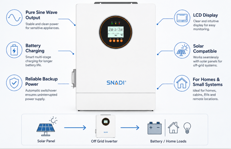
Definition and Fundamental Role of an Off-Grid Inverter
An off-grid inverter is an autonomous power conversion unit engineered to convert direct current (DC) generated by photovoltaic panels or stored in energy storage batteries into clean, regulated alternating current (AC) for off-grid applications.
Unlike grid-tied inverters that synchronize their AC output voltage waveform and phase angle with an existing public power grid, an off-grid inverter must establish its own voltage and frequency reference frame from scratch. It acts as the primary voltage source for the entire local electrical microgrid. In remote industrial locations, agricultural installations, telecom base stations, and off-grid residential homes, this device guarantees continuous power availability without needing a utility grid connection. The off-grid inverter manages complex power routing, taking power directly from solar arrays when available, feeding excess power to energy storage banks, and converting DC to AC when electrical consumption demands arise.
From an industrial application perspective, the off-grid inverter is the core intelligence of any standalone renewable energy platform. In practical field deployments, client requirements extend beyond simple DC to AC conversion. Systems must handle diverse load dynamics, ranging from sensitive microprocessor electronics to heavy inductive industrial equipment such as motor-driven pumps, compressors, and power tools. An off-grid inverter must continuously balance fluctuating power supply from renewable sources with unpredictable electrical consumption, ensuring system stability, power quality, and equipment protection under all operating conditions.
Modern off-grid inverter designs incorporate sophisticated digital signal processors (DSPs) to monitor system metrics continuously. These systems regulate output voltage, maintain fixed frequency parameters, manage battery bank discharge depth, and protect attached electrical loads against voltage sags, spikes, and total harmonic distortion. For mission-critical applications where utility power is entirely unavailable, choosing a high-reliability off-grid inverter design is essential to prevent system downtime and safeguard high-value industrial machinery.
Core Operational Mechanism of Off-Grid Power Systems
The core operational mechanism of an off-grid inverter relies on solid-state power electronic switching to convert DC power into a sinusoidal AC waveform, while dynamically managing battery charge states and load power distribution.
At the architectural level, an off-grid inverter takes DC input voltage from a battery bank or solar PV array and passes it through high-speed power electronic switches, typically Metal-Oxide-Semiconductor Field-Effect Transistors (MOSFETs) or Insulated-Gate Bipolar Transistors (IGBTs). These switching components are driven by Pulse Width Modulation (PWM) signals operating at high frequencies. By modulating the duty cycle of these pulses, the inverter generates a synthesized staircase waveform. Subsequent LC filtering circuits smooth out high-frequency switching harmonics, resulting in a clean pure sine wave AC output identical to, or higher quality than, standard utility power.
In a complete standalone solar installation, the off-grid inverter works alongside a Maximum Power Point Tracking (MPPT) solar charge controller and a battery storage system. During daylight hours, incoming solar radiation hits the PV array, producing variable DC voltage. The embedded or integrated MPPT charge controller regulates this voltage to efficiently charge the battery bank and power attached AC loads via the inverter stage. When solar generation drops below current consumption levels or vanishes completely during nighttime hours, the off-grid inverter instantly draws energy from the battery storage bank to power AC electrical loads without interruption.
Advanced units also incorporate dual power inputs and auxiliary generator auto-start controls. When battery voltage drops below a pre-set state-of-charge (SOC) threshold due to prolonged poor weather, the off-grid inverter can start an auxiliary diesel or gasoline generator. It can accept the generator's AC input, rectify it to charge the depleted battery bank, and pass through power directly to connected AC loads. To achieve complete operational autonomy across demanding remote sites, operators frequently deploy a fully integrated off grid hybrid solar inverter, which seamlessly unifies solar MPPT charging, generator management, battery storage, and pure sine wave inversion into a single compact power engine.
Key Technical Specifications and Engineering Parameters
Selecting and evaluating an off-grid inverter requires precise analysis of key electrical specifications, including continuous power capacity, surge capability, nominal DC voltage, efficiency curves, and total harmonic distortion (THD).
Continuous power capacity, rated in Watts (W) or Volt-Amperes (VA), dictates the maximum sustained electrical load the inverter can power indefinitely under standard operating temperature conditions. Surge power capacity, typically expressed as a multiple of continuous power (such as 2x or 3x for short durations), determines the inverter's capability to supply instantaneous inrush current required by inductive loads when starting electric motors, refrigeration compressors, or heavy power tools. High surge ratings prevent system voltage drops, tripping, or premature shutdown during high load switching events.
Efficiency curves represent another critical engineering parameter. Modern off-grid inverters achieve peak efficiency levels ranging between 93% and 97%. However, operational efficiency varies significantly depending on output load percentages and operating temperatures. Standard continuous operation around 50% to 80% of rated capacity maintains optimal thermal and electrical efficiency. Furthermore, total harmonic distortion (THD) must remain below 3% for linear loads and below 5% for non-linear loads to guarantee clean power quality and avoid overheating sensitive electronic hardware or causing operational hum in audio and communications equipment.
Specification Parameter | Typical Off-Grid Inverter Value Range | Engineering Significance in System Design |
Continuous Power Rating | 1 kW to 15 kW (Single Phase) / Up to 100 kW+ (Three Phase) | Determines the baseline AC load capacity the system can continuously supply. |
Peak Surge Capacity | 150% to 300% of rated capacity (10 ms to 10 seconds) | Supplies essential inrush currents needed to start inductive motor loads. |
Nominal DC Input Voltage | 12V, 24V, 48V, or High Voltage (100V - 500V DC) | Influences cabling thickness, system current losses, and battery bank configuration. |
Output Voltage & Frequency | 110V/120V (60Hz) or 220V/230V/240V (50Hz) Pure Sine Wave | Ensures compliance with local electrical equipment standards and safety rules. |
Peak Inversion Efficiency | 93% to 97% | Minimizes internal heat dissipation and maximizes usable solar power utilization. |
Total Harmonic Distortion (THD) | < 3% (Linear Loads) | Guarantees utility-grade power quality for sensitive electronics and medical units. |
Off-Grid Inverter Topology Comparison: Low-Frequency vs High-Frequency
Off-grid inverter architectures divide into low-frequency designs using heavy iron-core power transformers and high-frequency systems using compact electronic switching stages.
Low-frequency off-grid inverters use large iron-core toroidal or EI transformers operating directly at grid line frequencies (50Hz or 60Hz). This design provides high mechanical and electrical robustness. The massive magnetic mass of the low-frequency transformer acts as a physical energy buffer, enabling these inverters to deliver exceptional surge capabilities up to 300% of their continuous rating for several seconds. Consequently, low-frequency inverters are ideal for demanding industrial applications involving heavy induction motors, pumps, crushers, and severe inductive spikes. However, they are heavier, larger, and slightly less efficient at standby idle states.
High-frequency off-grid inverters replace bulky line-frequency transformers with smaller high-frequency ferrite transformers operating at frequencies above 20 kHz. This approach significantly reduces total physical weight, unit footprint, and manufacturing costs while boosting conversion efficiency. High-frequency inverters deliver superior power density and lower no-load standby power losses, making them highly attractive for residential solar installations, mobile applications, and light commercial setups. However, their physical surge capacity is typically limited to 150% to 200% of rated load for shorter durations compared to low-frequency alternatives.
When selecting topology for client projects, engineers evaluate application specific demands. European commercial and industrial clients, for instance, prioritize high efficiency, sleek compact design, advanced digital communications, and strict grid protection compliance. In contrast, heavy industrial applications in harsh off-grid environments often favor low-frequency designs for maximum fault tolerance. Where environmental versatility, dual grid interaction, and advanced power management are required, modern hybrid designs bridge these topologies. For robust installations across both grid-connected and standalone scenarios, deploying a versatile on off grid solar inverter ensures optimal power delivery across fluctuating energy conditions.
Critical Components and Internal Architecture Breakdown
The internal architecture of an off-grid inverter consists of power switching circuits, control processors, isolation transformers, filtering networks, and heat dissipation hardware.
The primary power conversion block features high-power MOSFETs or IGBTs organized in a full-bridge (H-bridge) circuit configuration. Controlled by high-speed PWM signals generated by a central Digital Signal Processor (DSP), these switches flip polarity thousands of times per second, transforming stable DC power into a high-frequency AC pulse stream. High-quality solid-state switching components are crucial for minimizing switching power losses and maintaining thermal stability under continuous heavy loads.
Internal Subsystem | Primary Component Electronics | Functional Responsibility in System Operations |
DC Switching Stage | MOSFET / IGBT Power Semiconductors | Executes high-speed switching to convert static DC voltage into raw AC pulses. |
Control Core | 32-bit Digital Signal Processor (DSP) | Generates precision PWM timing, controls feedback loops, and handles protection logic. |
Voltage Matching | Toroidal Low-Freq or Ferrite High-Freq Transformer | Steps up low DC battery voltage to line-level AC voltage and provides galvanic isolation. |
Output Filtering | Inductor-Capacitor (LC) Filter Network | Smooths out high-frequency PWM switching pulses into a pure sine wave AC output. |
Thermal Management | Extruded Aluminum Heatsinks & Variable Fans | Dissipates internal thermal energy generated by power electronics during operation. |
Following the H-bridge switching stage, raw AC pulses pass through an LC filter network consisting of precision inductors and capacitors. This filter suppresses high-frequency carrier noise, yielding a smooth sinusoidal output AC waveform. Galvanic isolation between low-voltage DC battery circuits and high-voltage AC load circuits is provided by the transformer, protecting sensitive battery management electronics from AC load transients, lighting strikes, and potential short circuits.
Control intelligence resides in high-speed 32-bit DSP controllers executing real-time closed-loop algorithms. These algorithms monitor voltage, current, internal temperature, and frequency thousands of times per second. If an abnormal operating condition occurs, such as a short circuit, thermal overload, battery over-discharge, or sudden load jump, the DSP adjusts PWM duty cycles within microseconds or safely disconnects the inverter output stage to prevent catastrophic hardware failure.
System Design and Sizing Principles for Standalone Applications
Designing an off-grid power system requires accurate calculations of total connected loads, peak surge requirements, battery bank storage capacity, solar array capacity, and ambient temperature derating factors.
The initial phase of system design demands a comprehensive load profile evaluation. Engineers sum the power consumption in Watts of all AC appliances operating simultaneously to establish the required continuous output rating of the off-grid inverter. Furthermore, starting surge currents for all inductive motor loads must be calculated. For example, a 1 kW air conditioning compressor may require up to 3 kW of instantaneous peak power for several cycles during motor startup. The inverter's surge capacity rating must accommodate these cumulative peak loads without voltage sags that could cause connected digital equipment to reset.
Next, nominal battery voltage selection directly influences total system efficiency and cabling costs. Small off-grid systems under 2 kW commonly operate on 12V or 24V DC battery banks. However, larger commercial and industrial off-grid systems operating between 3 kW and 15 kW generally utilize 48V DC or higher voltage DC buses. Operating at 48V reduces current by 75% compared to a 12V system for the same power output, drastically reducing resistive copper losses, voltage drop along wiring runs, and required conductor wire thickness.
Finally, environmental derating factors are vital for long-term system reliability. Operating in high ambient temperatures reduces the thermal heat dissipation capacity of solid-state electronics and heatsinks. An off-grid inverter operating in a 50°C desert environment may experience power derating of 10% to 25% compared to its standard 25°C rating. Engineers must account for site-specific thermal conditions, altitude, enclosure ventilation, and battery chemistry operational parameters during initial capacity design to prevent nuisance shutdowns during peak summer operation.
Integration with Hybrid Features and European Grid Standards
Modern off-grid inverters incorporate hybrid multi-mode operational flexibility, dual AC inputs, intelligent grid interaction, and strict compliance with European safety and enclosure standards.
Standard & Feature Category | Engineering Requirement & Standard | Operational Advantage in Off-Grid / Hybrid Systems |
Ingress Protection (IP Rating) | IP54 / IP65 Dust & Splash Resistance | Enables outdoor installation and protects internal electronics in dusty or rainy settings. |
European Grid Compliance | CE, VDE-AR-N 4105, EN 50549-1 | Ensures compliance with grid synchronization, safety disconnects, and harmonic limits. |
Dual AC Input Handling | Utility Grid + Auto Generator Control | Provides seamless backup power source switching when battery voltage drops low. |
Battery Compatibility | RS485/CAN Bus Closed-Loop BMS Communication | Optimizes charging parameters for Advanced LiFePO4 and Lithium-ion chemistries. |
The boundary between pure off-grid inverters and grid-tied systems has blurred significantly with the rise of hybrid power topologies. In modern commercial and residential infrastructure, customers often request systems that operate primarily off-grid to maximize self-consumption of solar energy, yet retain the ability to synchronize with the utility grid or an auxiliary diesel generator when solar generation is insufficient. These advanced hybrid units incorporate multi-mode priority settings, allowing users to prioritize Solar-First, Utility-First, or Battery-First power flow configurations depending on local energy tariffs and power reliability needs.
In the European market, environmental conditions and regulatory compliance drive inverter architecture decisions. European installations demand strict compliance with safety, electromagnetic compatibility (EMC), and grid-connection standards such as CE, EN 50549-1, and VDE guidelines. Furthermore, outdoor installations in coastal, agricultural, or industrial regions require robust weatherproofing to protect internal power electronics against dust, humidity, and moisture ingress. Deploying a specialized IP54 outdoor off grid solar inverter Euro standard unit guarantees reliable operation in challenging European outdoor environments without requiring specialized external protective shelters.
Why do engineering teams design off-grid inverters with IP54 or higher sealed enclosures and integrated dual-layer heat dissipation channels? From practical field experience, client feedback reveals that dust accumulation, insect infestation, and ambient humidity are leading causes of power electronic failures in remote off-grid sites. By isolating internal high-voltage PCB components inside a sealed IP54 compartment and utilizing external cooling fins, inverter operational lifespans increase dramatically, ensuring uninterrupted power availability in severe operational conditions.
Maintenance Tips and Preventive Protocols: To ensure long-term operational reliability in remote off-grid installations, perform visual inspections of thermal cooling fan assemblies every six months, checking for dust obstruction or mechanical wear. Verify all high-current DC terminal connections with a calibrated torque wrench annually to prevent resistive heating caused by thermal cycling vibration. Check that battery management system (BMS) communications remain fully synchronized via RS485/CAN protocols to ensure accurate state-of-charge calculation and prevent over-discharge.
System Maintenance and Preventive Operational Reliability
Preventive maintenance and robust thermal management are vital to maximizing the working lifespan of off-grid inverters in demanding standalone applications.
An off-grid inverter operates continuously under varying electrical loads and thermal conditions. Regular maintenance schedules prevent premature component aging, particularly for heat-sensitive elements like electrolytic smoothing capacitors and internal cooling fans. Routine inspection protocols should include verifying air intake cleanliness, checking thermal imaging profiles under full load conditions to spot elevated electrical resistance, and confirming that output voltage and frequency stay within specified nominal boundaries.
Furthermore, digital monitoring interfaces have revolutionized off-grid maintenance. Modern off-grid inverters feature Wi-Fi, GPRS, and RS485 communication interfaces that upload real-time operational diagnostics to cloud management platforms. Field engineers can remotely monitor battery state-of-charge, daily solar yields, ambient internal temperatures, fault event logs, and continuous load levels from anywhere in the world. This remote diagnostic capability enables proactive maintenance, allowing support teams to rectify minor operational anomalies long before they escalate into complete system outages.
In summary, the off-grid inverter is much more than a simple power converter; it is the central operational brain and power manager of any independent energy installation. By evaluating load dynamic profiles, matching DC input voltage configurations, prioritizing topology features, and deploying robust IP-rated enclosures, system engineers can build resilient off-grid power infrastructure capable of delivering continuous, utility-grade AC electricity to remote facilities worldwide.
