

The panel is in sunlight. The display shows PV voltage, yet charge current remains at zero. That reading does not prove the controller has failed. It means the system has reached a decision point. The controller may be waiting for usable PV power, holding a full battery, responding to a battery management system, limiting current for temperature, or following a setting that does not match the installed battery.
So how does a solar charge controller work in practice? It compares conditions on the array side with conditions on the battery side, then regulates energy transfer inside its electrical limits and charging algorithm. It can deliver available current, hold a target voltage, reduce output, pause, or stop. It cannot force a small or shaded array to produce rated power, and it cannot make an incompatible battery profile safe.
A charge cycle is the most useful way to understand that behavior. It turns an abstract definition into a sequence that an owner, installer, or buyer can observe. It also creates a disciplined troubleshooting method: identify the present stage, record the evidence, and consult the exact controller and battery manuals before changing a setting.
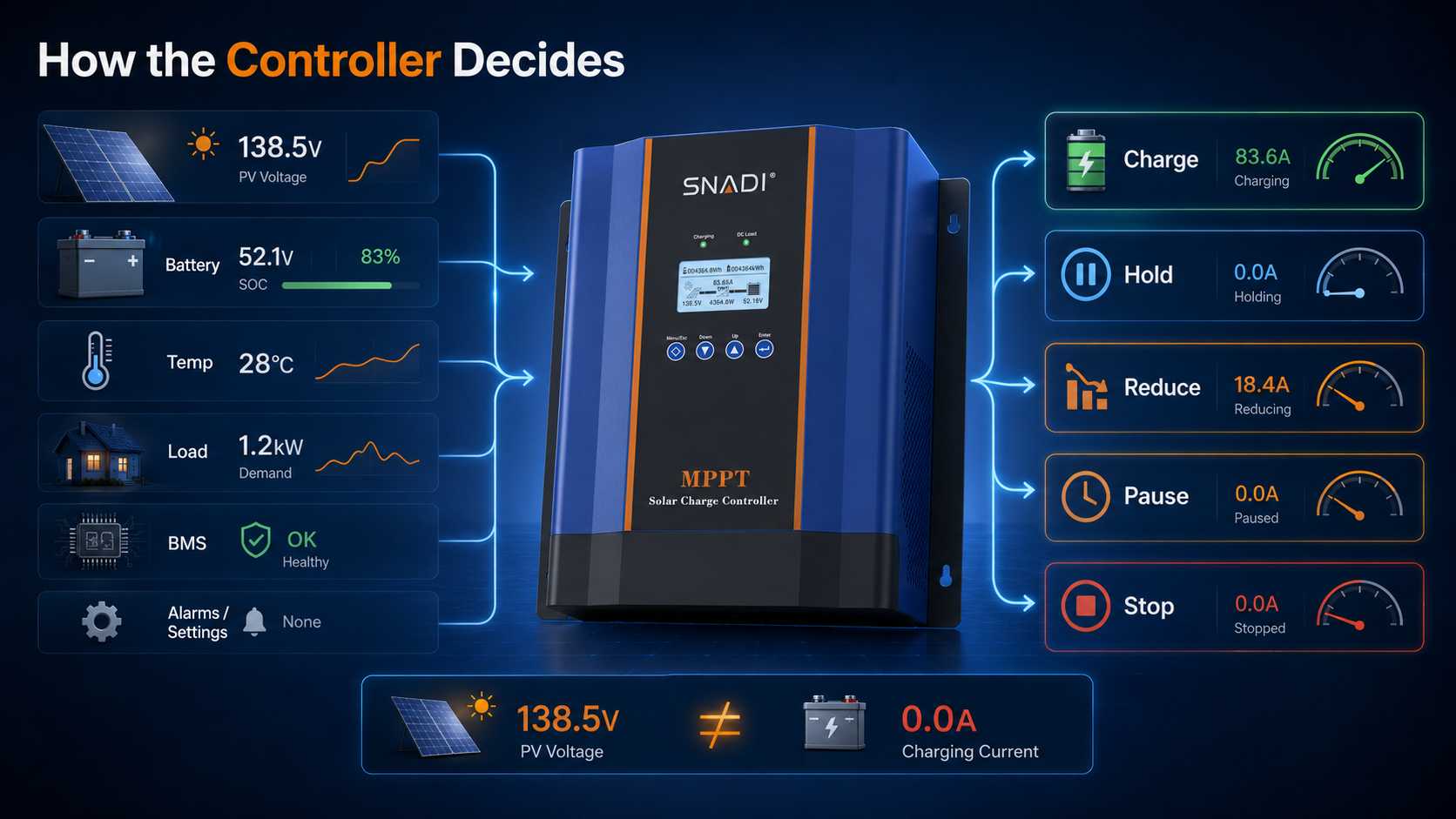
What the Controller Actually Controls
A small DC system has several actors. The PV array produces voltage and current that vary with irradiance, temperature, wiring condition and the load placed on the array. The controller accepts that input only within a defined window. The battery stores energy and sets limits for voltage, charge current and temperature. A lithium battery management system can allow, reduce or block charging. Loads consume energy at the same time, so controller output current and net battery current may not match.
These roles matter during fault finding. A display can show controller output while a separate battery monitor shows less current because a refrigerator, radio or inverter is using part of the energy. A controller is also not the same device as an inverter, although some hybrid inverters include an MPPT function. A separate controller still needs compatible wiring, protection, battery settings and coordination with every other charging source.
The controller therefore regulates a boundary, not an entire power system. It needs enough PV voltage and power to start, a battery that is present and permitted to charge, valid temperature conditions, and settings that agree with the battery requirements. When one condition is missing, reduced current or a stopped state may be the correct response.
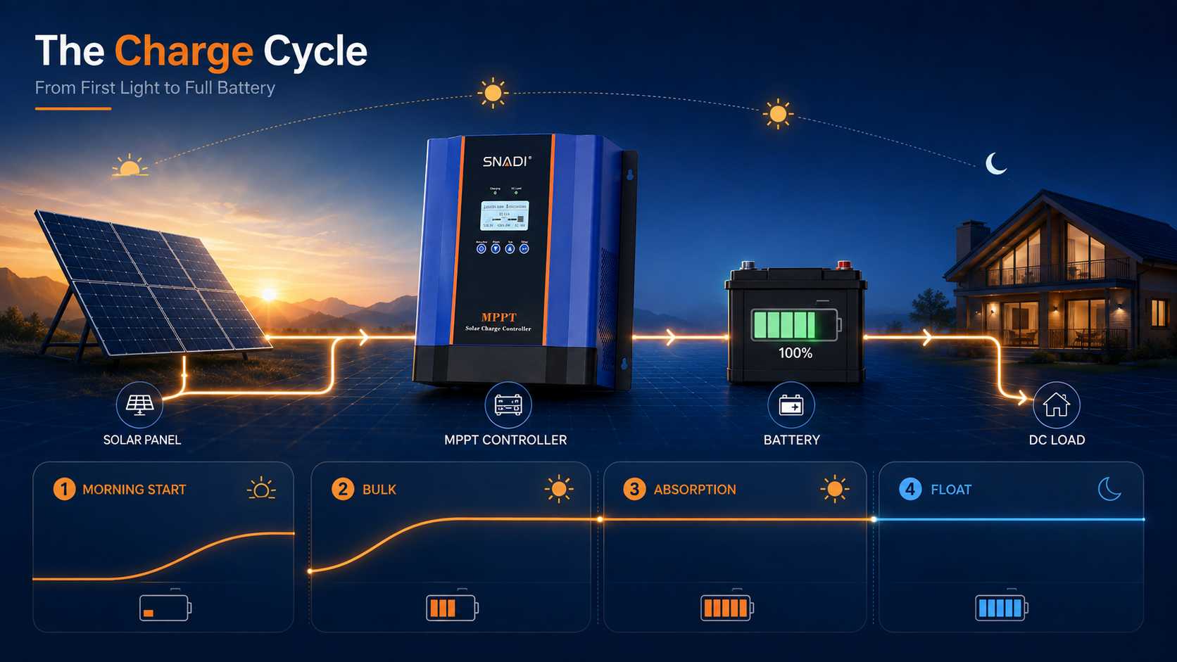
A Charge Cycle From First Light to Full Battery
Manufacturers use different labels and restart rules, but many controllers organize charging into recognizable stages. The purpose of the sequence is more transferable than any numerical threshold. Voltage targets, timers, tail current and temperature rules remain model and battery specific.
Morning Start
At first light, a module may show open circuit voltage before it can provide useful current. The controller waits until startup conditions are satisfied. Those conditions can include sufficient PV voltage above battery voltage, valid battery detection, an allowed temperature and no blocking command from a battery management system or external controller.
Record PV voltage, battery voltage, controller state and time before judging the result. A dark morning can delay startup without indicating damage. The same state near solar noon under clear conditions calls for closer checks. The United States Department of Energy explains that solar radiation at a location changes with time of day, season, landscape and weather.
Bulk
During Bulk, the controller normally delivers available charge current up to the lowest active limit. Battery voltage rises as energy is restored. Current may remain below the controller rating because the array is small, irradiance is weak, loads use part of the output, thermal reduction is active, or the battery and its management system permit less current.
Rated amperage is a ceiling, not a promise. A controller rated for 60 A does not create 60 A from an undersized array. It should not send that current into a battery that permits less. Buyers must treat the controller output limit and the battery charge current limit as separate design checks.
Absorption
When the configured voltage condition is reached, the controller may hold a target voltage while current falls. Lower current near the top of charge can be normal because the controller is regulating and the battery is accepting less. Loads and other charging sources can change what the controller observes at this stage.
Absorption duration can depend on time, prior battery condition, tail current or an external command. A copied voltage or timer value is poor evidence unless the battery manufacturer supports it and the controller manual explains how to enter it. This is where generic online settings create avoidable battery risk.
Float Stop and Restart
After the completion condition, a controller may maintain a lower Float voltage, stop charging, or follow an external command. If loads later pull the battery below a restart condition, another cycle can begin when the PV input is adequate. A zero current reading at this point can be expected behavior.
Read the Measurements Before Changing a Setting
A useful controller decision comes from four groups of evidence. Each group answers a different question, and each points to a different source of authority. Writing the readings down is faster than moving through menus from memory.
Evidence group | What to record | Decision it supports | Authority to check |
PV input | Voltage, current or power, weather, time and visible array condition | Whether usable solar power reaches the controller | Module string data and controller input limits |
Battery | Terminal voltage, temperature, chemistry and management system state | Whether the battery can accept charge | Battery and management system manuals |
Controller | Charge stage, output current, alarms, limits and communication state | Why output is full, reduced, waiting or stopped | Exact controller manual and saved settings |
System demand | DC load, inverter load and other charge sources | Where energy is going and why meters differ | Wiring diagram and meter definitions |
Build a sixty second operating record before making a change. Include the controller model, battery model, date, local time, weather, PV voltage, PV current or power, battery terminal voltage, charge current, charge stage, battery temperature, load and every active alarm. Photograph the current menu values so the original configuration remains recoverable.
For a remote home, communications site or small shop, that record has direct operating value. It can prevent an unnecessary service visit, shorten downtime and show whether the next action is more PV capacity, corrected wiring, a different controller, or a battery compatible configuration. Buying more hardware before identifying the active limit can increase both capital cost and service cost.
MPPT and PWM Solve Different Design Problems
An MPPT versus PWM decision starts with array voltage, battery voltage, cable length, climate, monitoring needs and budget. Both technologies regulate charging, but they use the PV input differently. Neither label removes the need to verify the operating window, maximum open circuit voltage and battery charge requirements.
Controller type | How it regulates | Where it can fit | What still needs checking |
PWM | Switches the array connection to regulate battery charging | Small systems where module voltage is appropriately matched to battery charging voltage | Voltage match, current rating, battery profile, cable loss and protection |
MPPT | Tracks an array operating point and converts input toward battery charging conditions | Systems using PV voltage above battery voltage or needing more string design flexibility | Tracking window, cold condition open circuit voltage, output current, thermal limits and monitoring |
For lead acid photovoltaic applications, IEC 62509 sets minimum functioning and performance requirements for battery charge controllers and connects controller reliability with battery life. Its stated scope matters. It does not prescribe lithium settings or authorize a universal charge profile.
A Safer Order for a Controller That Is Not Charging
Move from normal operating states toward faults. Do not start by raising charge voltage or repeatedly resetting the controller. Each step should either confirm a condition or narrow the next check.
1. Confirm the charge stage and battery condition. A full battery, Absorption, Float, external control or a battery management system command can explain low current.
2. Compare PV voltage under load with the startup and operating requirements for the exact controller. Open circuit voltage alone does not prove usable power.
3. Check battery permission and temperature. Review the management system state, selected chemistry profile and battery manual before changing voltage or equalization settings.
4. Review alarms, polarity, fuses, breakers, terminals and visible cable condition. Isolate the system by the manufacturer procedure before touching DC conductors.
5. Check external control and other charging sources. Communication commands or another charger can change stage behavior and make two meters report different current.
SNADI/SNAT Solar Engineer note:
Save alarm history and photograph every current setting before editing a menu. Change one verified item at a time. Uncertain polarity, damaged terminals, repeated overvoltage or an unclear shutdown procedure requires qualified electrical support, not trial and error.
Using the CM MPPT Range as a Screening Point
At SNADI/SNAT Solar, we use the published CM MPPT Solar Charging Controller specifications as a first screening point for residential, off grid and small commercial systems that need a separate controller. The listed range includes CM 30A, CM 40A, CM 50A, CM 60A, CM 80A and CM 100A models. It automatic recognition for 12 V, 24 V, 36 V and 48 V systems, PV input up to 150 V, an LCD and optional RS485 communication.
Those specifications do not choose a model by themselves. The selected controller current must fit the permitted charge current of the battery and management system. The PV string must remain within the applicable tracking range and maximum input voltage under the coldest design condition. Cable loss, protective devices, installation ventilation and monitoring responsibility must also be reviewed.
We focus on compatibility evidence rather than a single menu label. A buyer who provides module string data, battery model, system voltage, expected temperature range and required communications gives our engineering team enough information to screen controller amperage, PV input and monitoring needs. Final installation settings still follow the approved battery and controller documents.
Five Checks Before Selection and Setup
A controller can be correctly rated for current and still be wrong for the PV voltage or battery. Use these checks together, since each protects a different part of the system and a different part of the project budget.
1. Calculate PV string open circuit voltage at the lowest expected module temperature, then compare it with the controller maximum input limit.
2. Check PV operating voltage against the applicable tracking window for the selected battery system voltage.
3. Match controller output current with battery and management system charge limits, cable capacity, fuses and breaker protection.
4. Confirm chemistry profile, temperature behavior, Float policy and equalization policy from the battery manufacturer.
5. Confirm that display data, error codes, communication options and service documents will be available to the owner or maintenance team.
Selecting only by amperage can leave the PV string incompatible. Selecting only by a lithium menu label can leave the charge profile unsuitable. Selecting only by purchase price can raise operating cost when fault history, communication data and service documents are missing. A sound purchase decision freezes all of these boundaries before a model is ordered.
Conclusion
The solar charge controller working principle becomes useful when it is read as a sequence. The controller waits for usable PV input, supplies available current during Bulk, regulates voltage during Absorption, and then maintains, stops or restarts charging according to the installed algorithm and battery permissions. A low current reading can be normal, but it should be explained by evidence.
When charging looks wrong, begin with the PV string, battery chemistry, battery management system state, controller stage, loads and alarms. Do not begin with a copied voltage setting. For a compatibility review, provide the module string data, controller model, battery model, system voltage, expected temperature range and sixty second operating record. That information supports a practical model and settings review without assuming that one configuration fits every battery.
✉️Email: marketing@snadi.com.cn
Website:
☎️WhatsApp / WeChat: +86 1803929353

FAQ
It measures battery and system conditions, then limits current, holds a configured voltage, changes stage or stops according to its algorithm and external controls. Safe operation still depends on correct settings and a compatible battery.
Why does a solar charge controller stop charging?
Why can PV voltage be higher than battery voltage?
Can one setting profile serve lithium and lead acid batteries?
How should controller amperage be selected?
Does a solar charge controller work on cloudy days?