

A remote shop can lose refrigeration, lighting, communications, or pump operation because a small charging controller was selected from its ampere label and installed without checking the rest of the direct current system. The controller may cost less than the inverter or battery bank, yet a mistake at this point can lead to damaged batteries, lost trading hours, generator use, or a technician trip that costs more than the hardware.
We start with the duty the system must perform. A telecom cabinet, security system, water pump, cold room, and workshop motor do not create the same recharge target. For example, a site with a 1.2 kW refrigeration load plus 300 W of controls and lighting needs about 9 kWh for six hours of operation before conversion losses and reserve margin are added. The charge controller does not feed that alternating current load directly. It regulates the PV energy that restores the battery after the backup period.
Before approving a controller, record these project inputs:
· Battery bank voltage, battery chemistry, and permitted charge current
· PV array power, operating voltage, and open circuit voltage
· Daily energy that must be restored within the available solar window
· Maximum controller current and any required derating
· Ambient temperature, ventilation, enclosure conditions, and service access
This prevents a familiar procurement failure: the current rating looks adequate, but the PV string voltage exceeds the input limit, the battery profile is wrong, or the available solar hours cannot restore the energy used overnight.
IEA PVPS reported about 2,973 GW of cumulative PV capacity by the end of 2025, including about 698 GW added during that year. At that scale, installation records and repeatable checks are not paperwork for its own sake. They reduce faults across distributors, installers, and service teams.
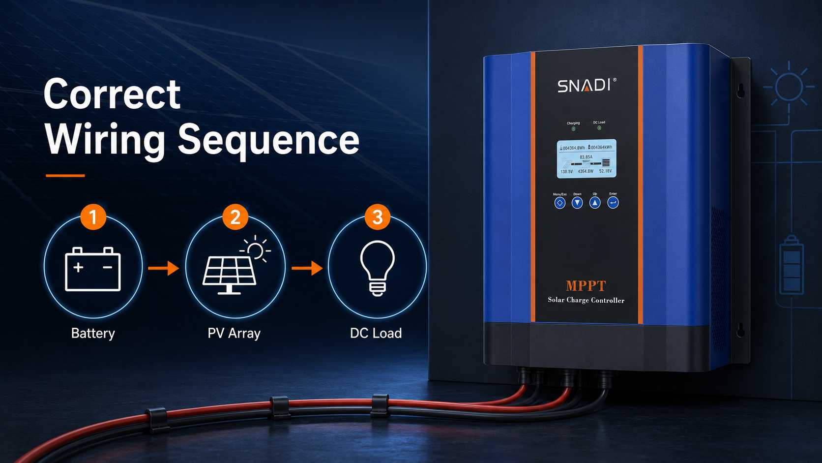
The wiring order in sixty seconds
For most battery powered solar charge controllers, establish the battery circuit first. Confirm that the controller starts and identifies the expected system voltage. Connect the PV circuit second, then connect only the direct current loads permitted by the controller. During disconnection, remove the load, isolate the PV circuit, and remove the battery connection last. The battery gives the controller electronics a stable reference. Energizing PV first can prevent correct startup on some models and can damage equipment that was not designed for that sequence.
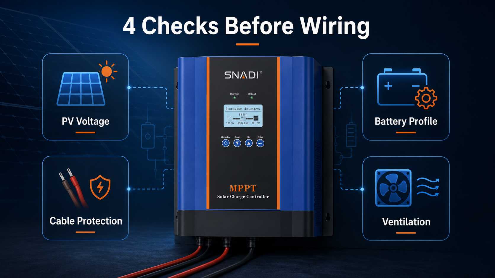
Four checks before any cable is connected
Confirm PV open circuit voltage in cold conditions
The highest PV string voltage must stay below the controller input limit at the lowest credible site temperature. Module open circuit voltage rises as temperature falls. A string that appears acceptable at standard test conditions can cross the controller limit on a cold morning.
Use the module datasheet temperature coefficient, the number of modules in series, and a defensible minimum site temperature. Do not substitute array wattage for this calculation. Wattage indicates energy potential. Open circuit voltage determines whether the input stage can tolerate the string.
Match battery voltage, chemistry, and charge limits
Nominal voltage is only the first check. Lead acid batteries can require bulk, absorption, float, equalization, and temperature compensation settings. Lithium batteries can require a documented charge voltage, current limit, low temperature restriction, and clear battery management system behavior. Automatic system voltage recognition does not prove that the correct battery chemistry has been selected. Record the active profile and every custom value in the commissioning sheet. Do not enable equalization unless the battery manufacturer permits it.
Size current, cable, and protection as one package
Controller current affects conductor size, voltage drop, terminal capacity, heat, fuse rating, breaker rating, and service access. A fuse should not be chosen from the controller label alone. The designer must also consider conductor rating, equipment instructions, expected current, local rules, and the interrupting capacity of the protective device.
IEC 62548 1 covers PV array direct current wiring, protection devices, switching, and earthing provisions. The practical lesson for buyers is simple: cable, disconnects, overcurrent protection, and earthing method belong in the same technical review, not in separate purchase decisions.
Check location, cooling, and service access
A controller that relies on natural convection needs clear airflow. Keep it away from direct sun, water, corrosive vapor, battery gas, heavy dust, and combustible material. Do not treat an enclosure as suitable for outdoor use unless the published protection rating and the installation arrangement support that conclusion. Leave enough room to inspect terminals, read the display, and operate disconnects. Control cable bends and do not let cable weight pull on terminals. Orientation, clearance, terminal torque, and temperature limits must come from the manual for the selected model.
How to complete solar charge controller installation
Isolate every source and verify polarity
Open the battery breaker, PV disconnect, and load disconnect. Cover or isolate exposed modules where practical. Use a meter to confirm the voltage and polarity of each conductor before it reaches a terminal.
Label positive and negative conductors before routing them into the enclosure. Reverse polarity protection can reduce equipment damage, but it does not replace correct workmanship. A battery can deliver enough current to create severe heat and arcing through an accidental short circuit.
Connect the battery circuit and confirm startup
Mount the controller and route the battery conductors while the battery breaker remains open. Install the specified fuse or breaker near the battery positive connection when required by the design and local rules.
Prepare the cable ends correctly, confirm polarity again, and tighten the terminals to the value in the product manual. Close the battery breaker only after the connection is complete and guarded against accidental contact. Check the displayed battery voltage rather than assuming automatic recognition is correct.
Connect PV inside the permitted voltage window
Measure the PV string open circuit voltage with the PV disconnect open. Compare the measured value with both the design calculation and the controller limit. If the result is higher than expected, stop and inspect string length, module type, polarity, and the temperature assumption.
Connect the PV conductors while the disconnect remains open. Once the battery circuit is stable and the battery settings are confirmed, close the PV disconnect. The display should show PV voltage and charging current when irradiance and battery state permit charging. Zero current is not automatically a fault when the battery is full, the array is shaded, or a battery protection limit is active.
Configure, energize, and document commissioning
Connect only loads that are permitted by the controller load output. Large inverters, pumps, compressors, and other high current equipment normally connect to the battery bus through their own protection. A small load terminal should not be used as a convenient supply point for equipment with unknown starting current.
Record the following commissioning results:
1. Battery voltage at the battery and at the controller
2. PV voltage before and after energization
3. Battery profile, voltage targets, and charge current limits
4. Charging current under known solar and battery conditions
5. Terminal temperature after initial operation
6. Active alarms, error codes, and load output status
7. Communication and monitoring test results
8. Cable strain, terminal condition, model, settings, and test date
SNADI/SNAT Engineer Tip:
Take one clear photograph of the finished terminal area and one photograph of the protection layout. Store them with the measured PV voltage, battery voltage, and charging current. A visual record often reduces diagnosis time when a remote technician later reports that the controller is not charging.
Compare design options before purchasing hardware
The controller with the lowest purchase price does not always create the lowest project cost. A separate MPPT controller can simplify replacement and support a flexible PV arrangement, but it adds direct current components and commissioning tasks. A hybrid inverter with integrated MPPT can reduce the number of major boxes, yet replacement can be more expensive when one charging function fails.
System design option | Relative CAPEX | Typical OPEX | Buyer value | Main operating risk |
Separate MPPT controller and inverter | Medium | Low to medium | Flexible charging design and easier component replacement | More direct current wiring, protection, and commissioning work |
Hybrid inverter with integrated MPPT | Medium to high | Low | Fewer major boxes and coordinated backup control | Dependence on the full unit and tighter PV input matching |
PWM controller for a small basic system | Low | Low | Simple charging where PV and battery voltage are closely matched | Lower energy harvest and limited array flexibility |
Oversized controller without a documented need | High | Low | Unused current margin | Capital is tied up while battery, PV, or load mismatch remains |
For a small commercial buyer, operating risk includes spoiled stock, interrupted production, generator fuel, technician travel, and the time required to isolate a fault. A controller that prevents one remote service visit can justify a higher purchase price. The reverse is also true: paying for unused current capacity does not correct a weak battery profile or an unsafe PV string.
Where the SNADI/SNAT Solar CM MPPT Solar Charging Controller fits
We use the SNADI/SNAT Solar CM MPPT Solar Charging Controller as a separate charging option for residential, off grid, and small commercial systems where the PV array and battery need a dedicated MPPT controller. The public product page lists CM 30A, CM 40A, CM 50A, CM 60A, CM 80A, and CM 100A models. It can automatic recognition for 12 V, 24 V, 36 V, and 48 V systems, PV input up to 150 V, LCD monitoring, optional RS485 communication, natural convection cooling, and several protection functions.
Those specifications create a screening framework, not an automatic selection. The current rating must fit the permitted battery charge current. The 150 V input limit must be checked against cold condition open circuit voltage. Optional communication can reduce service travel where the monitoring system and operating process are prepared to use it.
Consider a 48 V battery system with about 3 kW of PV. The CM 60A lists up to 3,400 W of solar input for a 48 V system and an MPPT operating range from 65 V to 150 V. That information narrows the candidate list, but the final decision still requires the module string calculation, battery charge limit, cable design, protection plan, and expected recharge window.
Troubleshoot the symptom, not the product label
A controller fault is easier to isolate when the technician starts from the observed symptom and measured values. Replacing the controller before checking voltage, protection, and settings can add cost without removing the cause.
· Blank display: Check battery voltage, breaker state, fuse continuity, polarity, and terminal contact. Many controllers cannot start from PV alone.
· Controller is on but the battery is not charging: Check PV voltage, PV disconnect state, battery state of charge, temperature limits, battery management system status, and active fault codes.
· PV voltage is present but charging current is zero: Confirm whether the battery is already near its target voltage. Then inspect cable continuity, current limits, charging stage, shading, and remote control settings.
· Load output is off: Check low voltage disconnect, timer settings, light control mode, load current, and short circuit alarms. Do not bypass a protection setting until the cause is known.
· Controller is hot or shuts down: Review airflow, ambient temperature, cable size, terminal tightness, charging current, and mounting orientation. Discoloration, odor, damaged insulation, or repeated shutdown requires immediate isolation and technical review.
Make maintenance and handover part of the order
A reliable installation includes records and service responsibilities, not only hardware. Ask the supplier or installer to provide the evidence needed to maintain the system after the commissioning team leaves.
· Product datasheet and installation manual
· PV string calculation
· Battery profile and charge limit record
· Cable and protection schedule
· One line diagram
· Commissioning values and photographs
· Monitoring access and alarm responsibility
· Spare fuse and replacement procedure
· Warranty conditions
· Technical support contact path
Inspect terminal condition and cable temperature after the first operating day, again after the first month, and then at the interval required by the product and site conditions. Dust, corrosion, vibration, heat, and battery service can change an installation that was correct on the day of handover.
For remote sites, monitoring is an operating cost control. An alarm that separates low PV voltage, battery protection, and excess temperature can prevent an unnecessary visit. Monitoring still needs an owner, an escalation rule, and access to the original settings. Data without an agreed response process does not reduce downtime.
Conclusion
Solar charge controller installation works when the controller is treated as one part of the complete direct current charging system. Define the load and recharge duty, calculate cold condition PV voltage, confirm the battery profile, size cable and protection together, follow the approved connection order, and keep measured commissioning results.
The SNADI/SNAT Solar CM MPPT Solar Charging Controller can fit residential, off grid, and small commercial systems when its current rating, PV voltage limit, battery settings, enclosure conditions, and communication option match the site. It is not the right choice simply because a larger model is available.
Before purchase, prepare the module datasheet, string layout, battery model, load profile, installation environment, and required recharge time. Our engineering team can review those inputs and identify whether the CM MPPT Solar Charging Controller range fits the operating task. For a project review, use our technical contact page.
✉️Email: marketing@snadi.com.cn
Website:
☎️WhatsApp / WeChat: +86 1803929353

FAQ
For most battery powered controllers, connect and verify the battery first, connect the PV array second, and connect approved loads last. Reverse the order during disconnection. Use the selected controller manual when it specifies a different sequence.
Can an inverter connect to the controller load terminal?
What happens when PV open circuit voltage is too high?
Does automatic battery recognition select the correct chemistry?
Why is the controller powered but not charging?
How should controller current be selected?
Can two controllers charge one battery bank?
When should an installer stop and request engineering review?